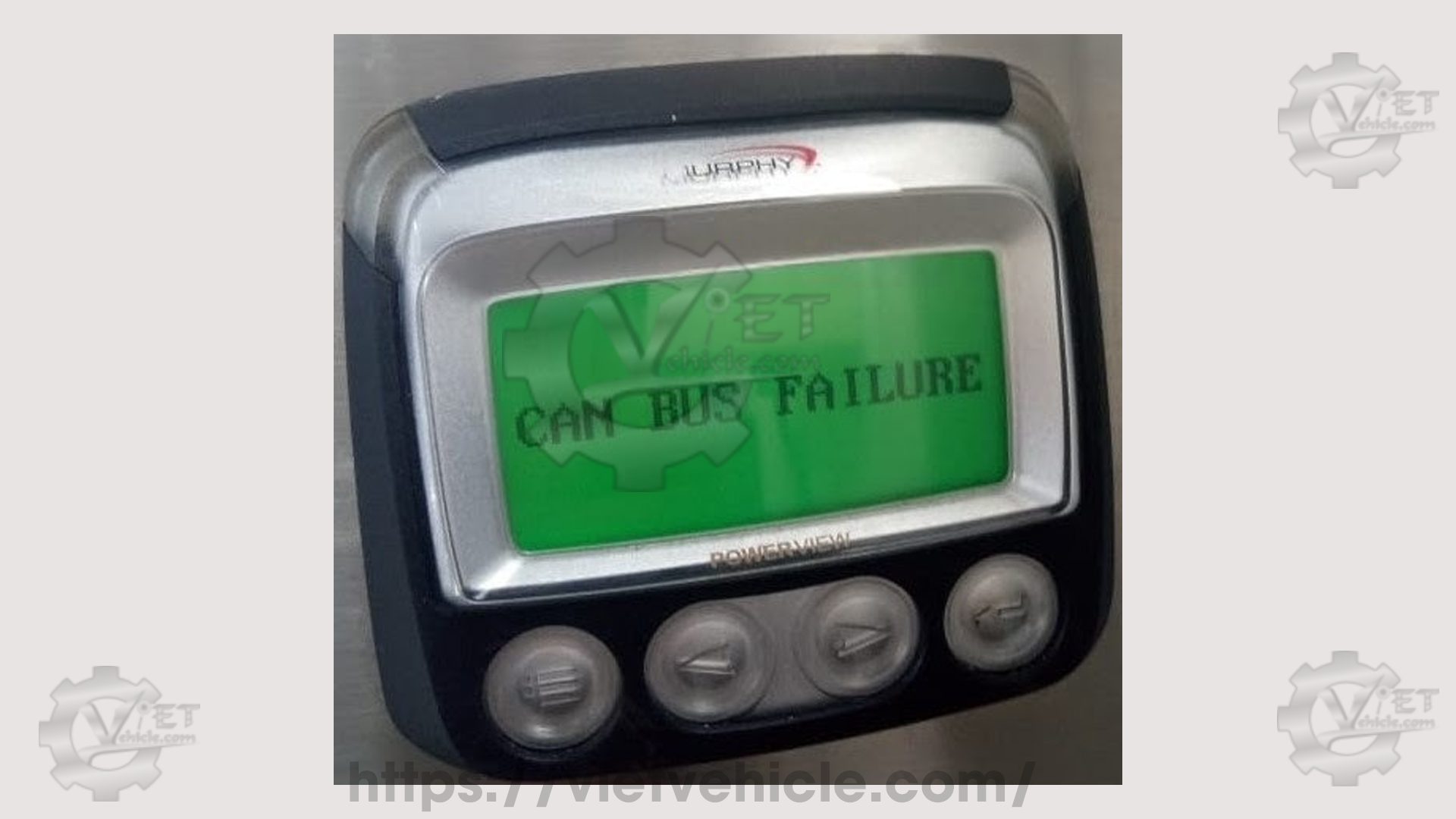
Figure 1.1 – CAN bus failure (Murphy PowerView)
Definitions of CAN bus:
Controller area network (CAN) is a serial bus that connects multiple electronic control modules (ECMs) or components to send or receive messages for proper machine/engine operation. This data link consists of two copper wires twisted as a pair, with approximately one twist per inch (40 twists per meter). The twisted pair is sometimes shielded. One wire is designated as CAN high (+), and the other as CAN low (-). The CAN data link facilitates real-time communication between ECMs, displays, service tools, and other components requiring network communication.
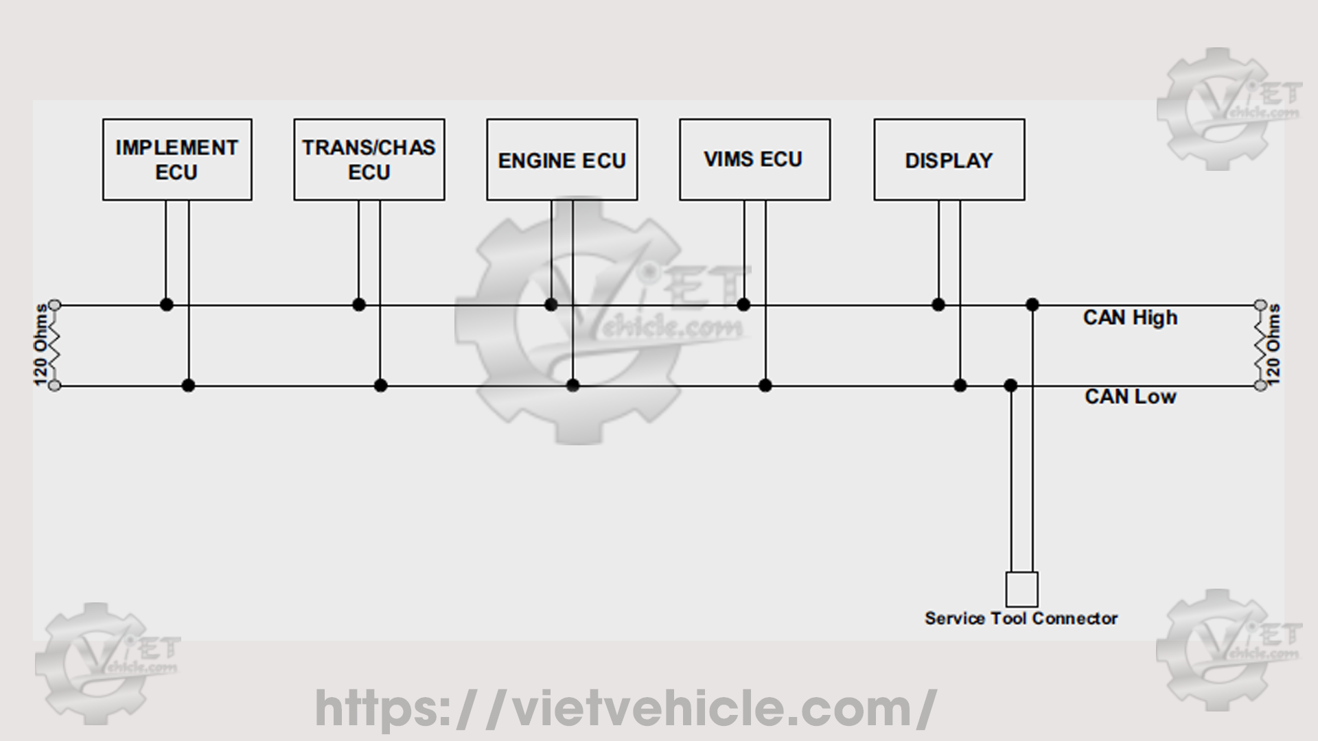
Figure 1.2 – A typical CAN bus
CAN is a simple two-wire differential serial bus where information is transferred using a differential voltage between CAN high and CAN low. The voltages of both CAN high and CAN low are relative to the shield or ground. The differential voltage relationship is defined by the formula:
*CAN diff = CAN high – CAN low
CAN buses have two logic states: dominant and recessive. Typically, the voltage level for a recessive state (logic “1”) is 2.5 V for both CAN high and CAN low. The voltage levels for a dominant state (logic “0”) are 3.5 V for CAN high and 1.5 V for CAN low. When the bus is idle, the voltage level is recessive (2.5 V).
The CAN bus is terminated with a 120-ohm resistor at each end to maintain a total circuit impedance of 60 ohms (two 120-ohm resistors in parallel = 60 ohms).
CAN bus failure – engine controller
When this diagnostic code occurs, the following responses occur:
The engine display does not detect the ECM on the CAN bus (J1939 CAN system).
The engine does not start (cranking only).
A. Murphy PowerView display:
CAN bus failure, as shown in Figure 1.1
No parameter received
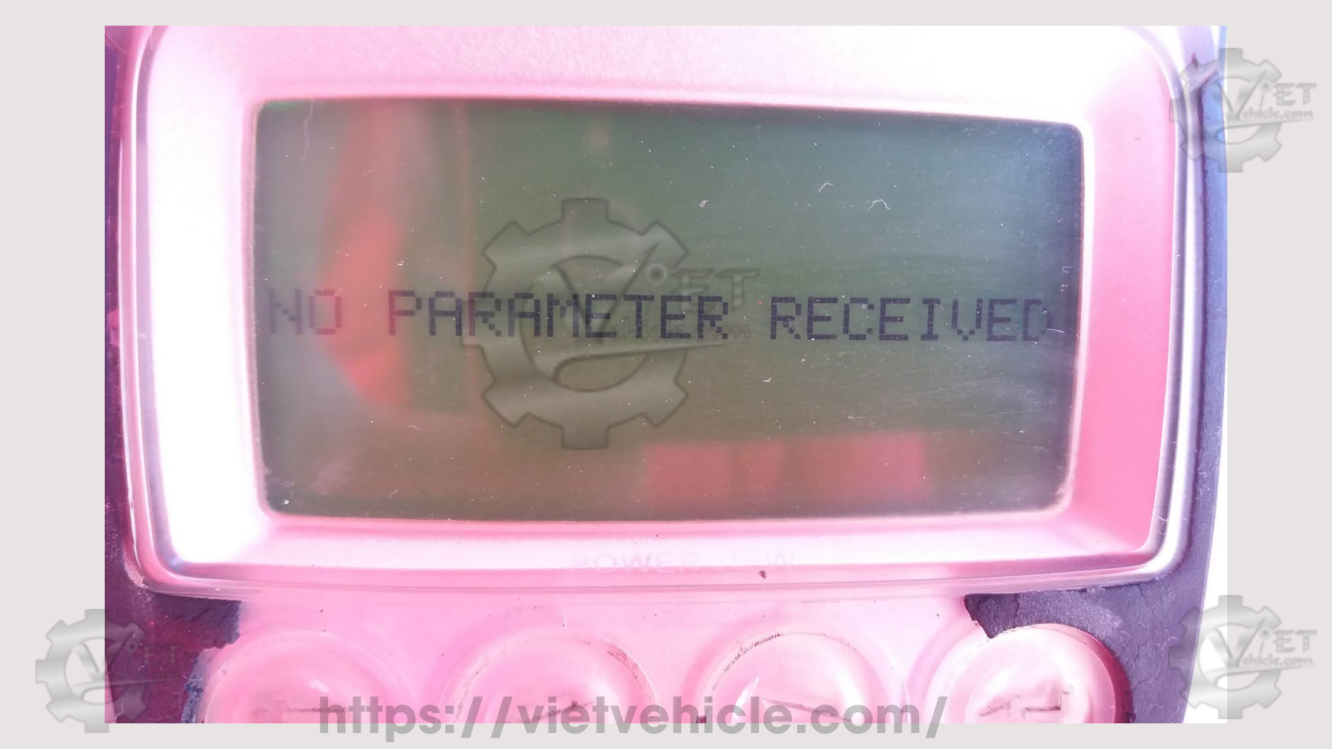
Figure 1.3 – No parameter received
No data for all engine parameters
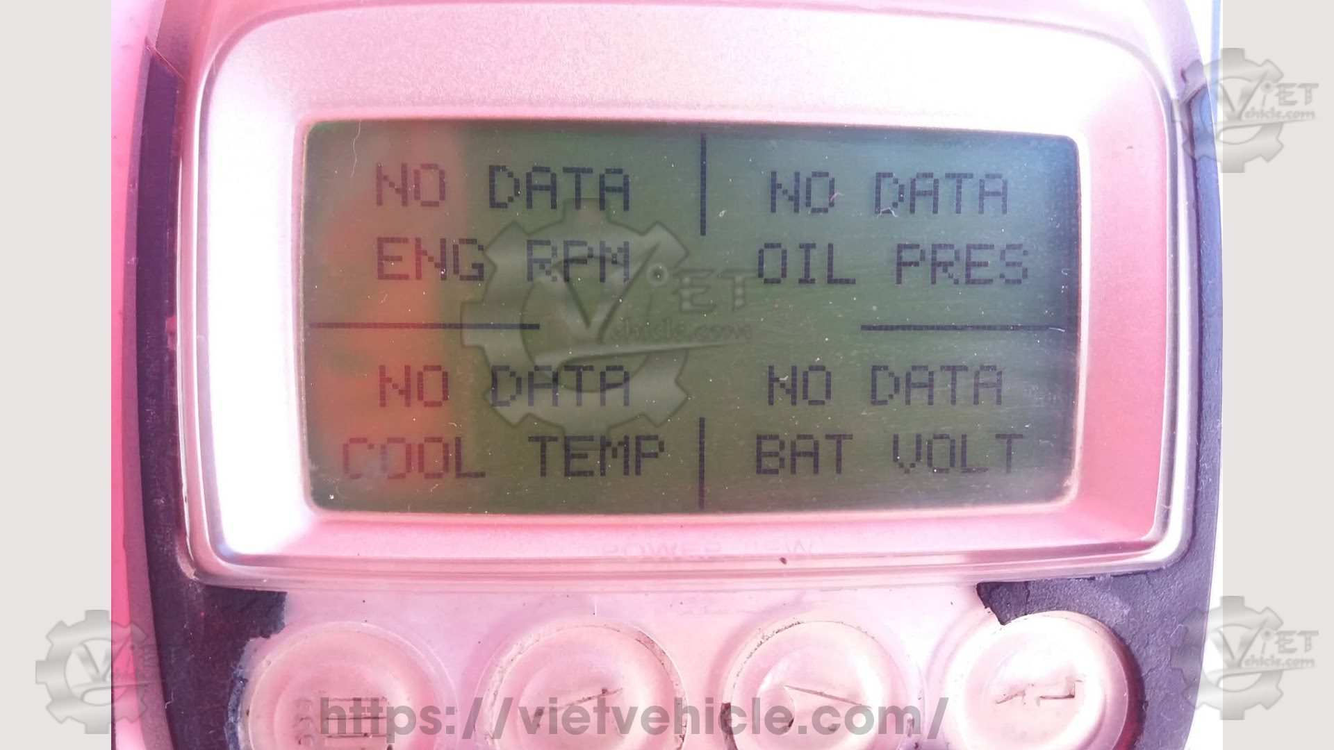
Figure 1.4 – No data (all parameters)
B. CAT Messenger display:
Only “Engine speed” and “Desired engine speed” are displayed with **** values.
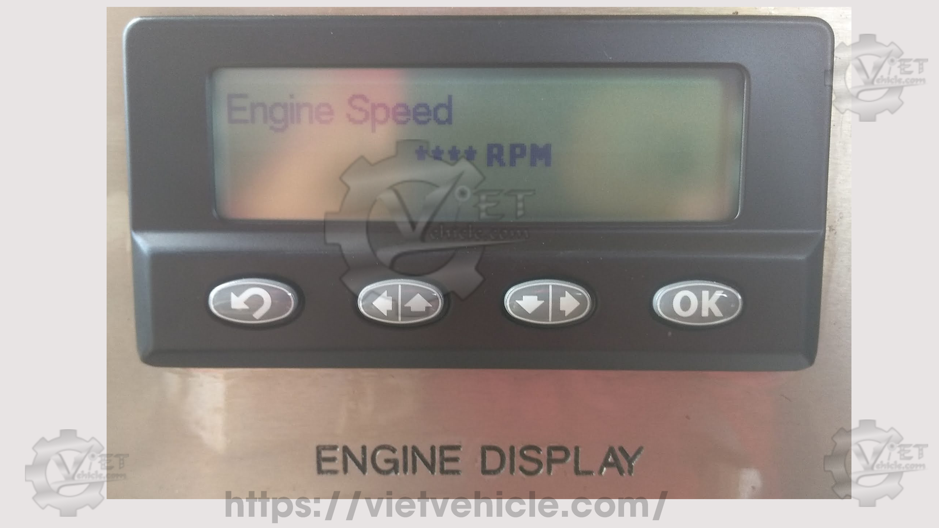
Figure 1.5 – Engine speed (**** RPM)
C. Electronic engine commander (EEC) on Detroit engine:
EEC’s information center message display: “EEC data fault.”
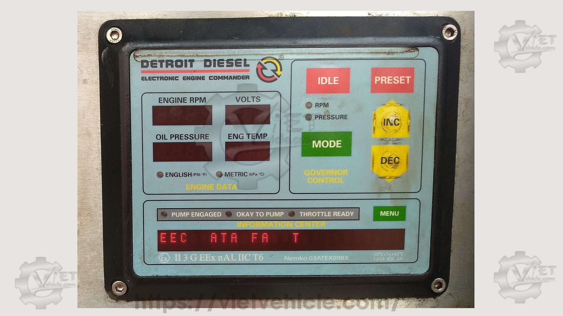
Figure 1.6 – EEC data fault
D. Detroit Diesel – electronic controls (electronic display module/EDM) on Detroit engine:
All parameter values are displayed as 0 (zero).
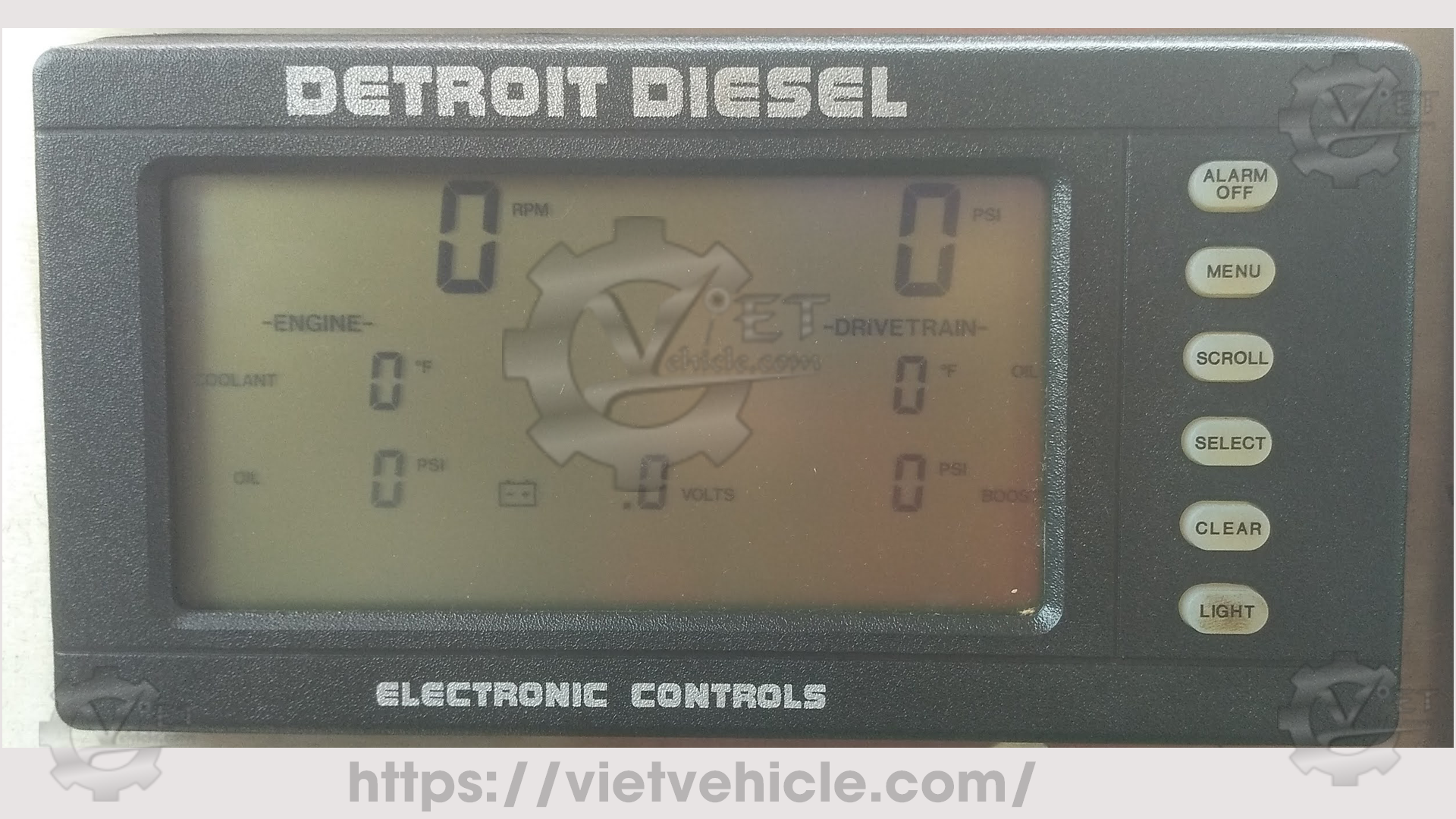
Figure 1.7 – EDM (zero values)
Perform the following test procedures:
Test step 1: Test the harness
Turn the main disconnect switch to the OFF position.
Inspect all harness connections related to the CAN bus. Ensure connectors are clean and secure.
Check each pin and socket of the engine harness connector to confirm proper installation.
Test step 2: Check the termination resistors
Measure the resistance of the CAN bus (expected result: 120 ± 12 ohms).
Test step 3: Check the input voltage
Measure the input voltage to the ECM for both (+) “battery unswitched” and “battery switched (keyswitch/ignition),” and the (-) battery/ground.
Contact Us
Whatsapp: +84.858.966.333
Facebook: VIETVehicle Remote Delete Service
YouTube: VIETVehicle – ECM Delete Tuning
Tiktok: VIETVehicle.com
Website: VIETVehicle.com

