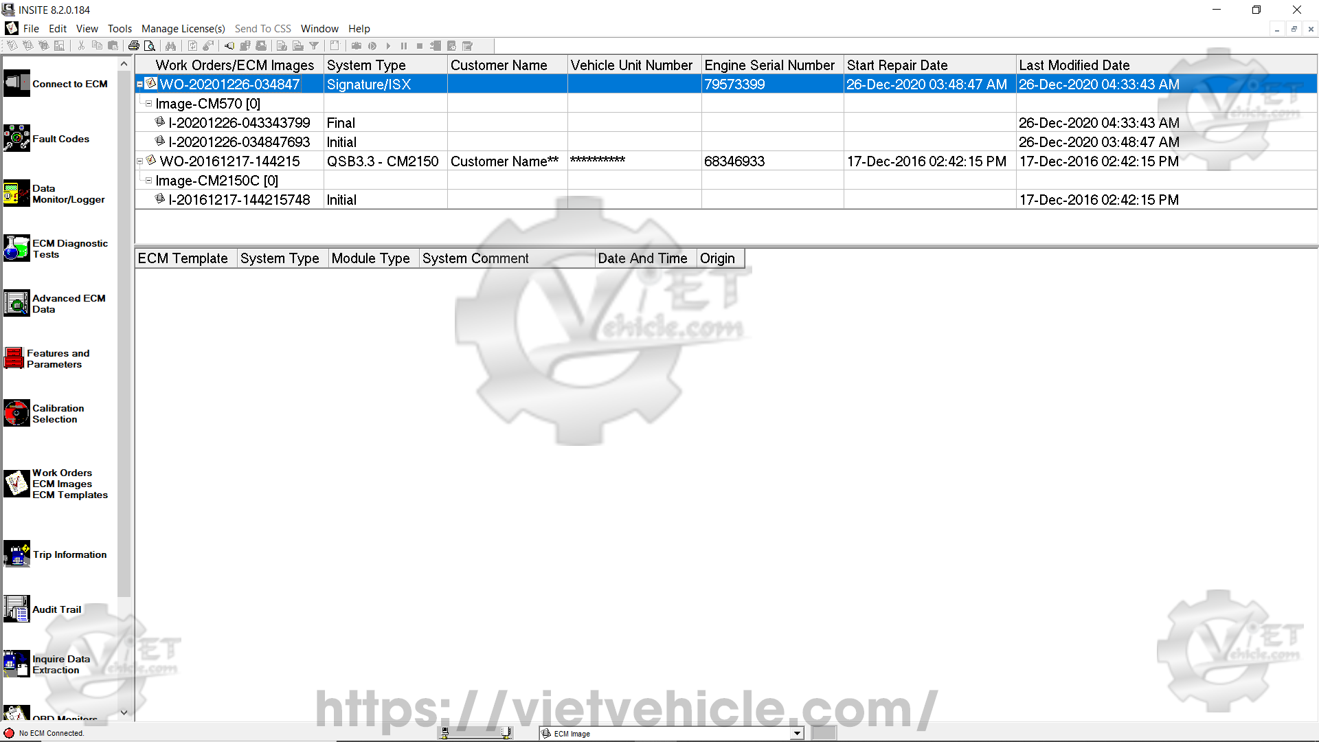
Figure 1.1 – Work orders/ECM images
Work orders – about
Work orders record and display ECM history, allowing technicians to reference previous ECM settings. Each work order contains one or more images, which are snapshots of all data accessible through INSITE™.
The Work Orders window is used to manage work orders, images, and templates. It consists of two sections:
The upper section displays work orders and summary information.
The lower section shows templates.
To open the Work Orders window, select Work Orders from the Viewbar (refer to Figure 1.1). When connected to an ECM or simulator, INSITE™ will only display work orders and images linked to that specific engine serial number and will only show templates for that ECM type. If not connected, all work orders and templates will be displayed.
By default, work orders are sorted by the last modified date, with the most recent ones appearing at the top. You can sort the list by any column by clicking the column header. Clicking the header again reverses the sorting order. Columns can also be repositioned by dragging them.
INSITE™ can be set to automatically start the work order creation process when connecting to an ECM or simulator. When enabled, the system will also begin the image creation process before disconnecting. This automatic process can be canceled if a work order is not needed. Follow these steps to enable or disable Work Order Mode:
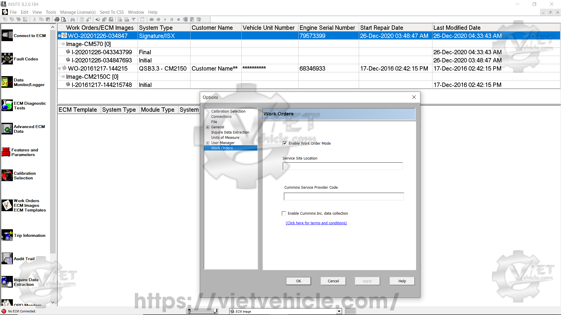
Figure 1.2 – Enable work order mode
Select Tools > Options from the menu bar.
In the Options window, select Work Orders from the left panel.
On the Work Orders screen, check or uncheck the Enable Work Order Mode box as needed.
Enter a Service Site Location if required.
Click OK to save changes and close the window.
Work orders – parameters
The upper section of the Work Orders window contains a table displaying summary information recorded when work orders and images were created. The table has seven columns, explained below:
Work orders/ECM images – Displays the work order name. A default name is generated using the format “WO-” followed by the year, month, day, hour, minute, and second when the work order was created. Example: “WO-20201226-034847” was created on December 26, 2020, at 03:48:47 AM.
System type – Displays the system type obtained from the ECM.
Customer name – Displays the customer name retrieved from the System ID and Dataplate.
Vehicle unit number – Displays the vehicle unit number retrieved from the System ID and Dataplate.
Engine serial number – Displays the engine serial number retrieved from the System ID and Dataplate.
Start repair date – Displays the date and time the first image was created in the work order.
Last modified date – Displays the date and time the most recent image was created in the work order.
Work orders – right-click menu
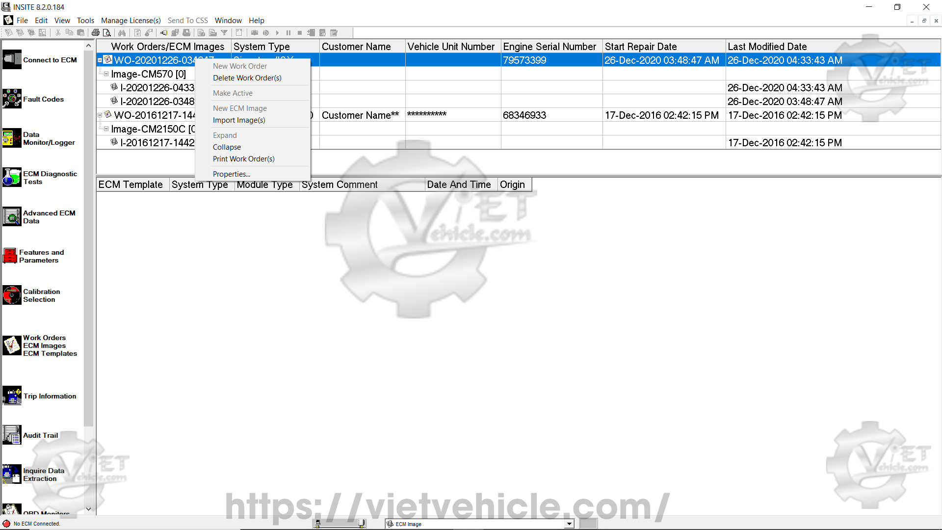
Figure 1.3 – Right-click menu
New work order – Opens the Work Order Wizard to create a new work order.
Delete work order(s) – Deletes all data records linked to the selected work order(s).
Make active – Activates a different work order. New ECM images will be attached to the active work order.
New ECM image – Creates an ECM image for the selected work order.
Import image(s) – Imports a saved ECM image file into the Work Orders window. (Read More: ECM images on Cummins INSITE™ software.)
Expand – Expands the selected work order to display its ECM images. Alternatively, click the expand icon next to the work order name.
Collapse – Collapses the selected work order, hiding its ECM images. Alternatively, click the collapse icon next to the work order name.
Print work order(s) – Prints one or more work orders.
Properties – Displays work order details. Editable fields can be modified by double-clicking the edit box. Additional information can be added to Technician’s Notes by clicking inside the notes section.
Print ECM image(s)
Select this option to print selected ECM images. Multiple images can be printed by holding Ctrl while selecting the images. Each image will be processed separately.
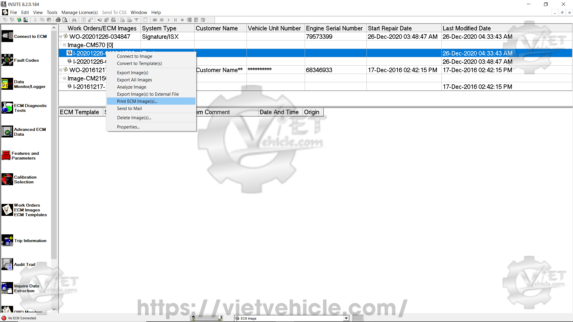
Figure 1.4 – Print ECM image(s)
A Print ECM Images window will appear. All features will be selected by default for printing and listed in the right-hand window.
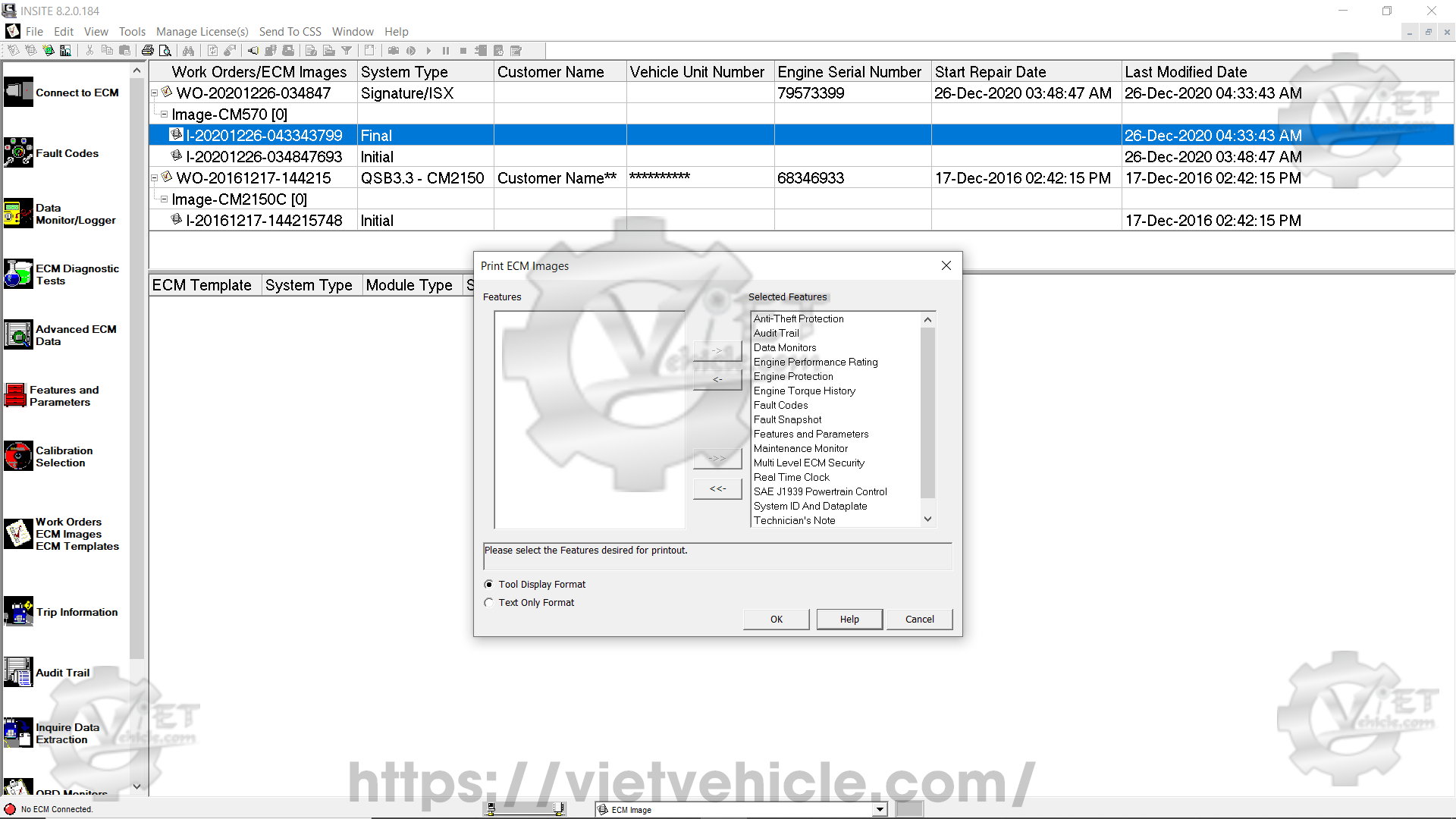
Figure 1.5 – Selected features
- Add or remove individual features using the “<-” and “>-” buttons.
- Add or remove all features using the “<<-” and “>>-“` buttons.
- Choose a print format:
Tool display format – Prints data as shown in INSITE™.
Text-only format – Prints data in table format.
Click OK, then follow the print wizard steps. (Example file: ECM Images CM570 Final.pdf.)
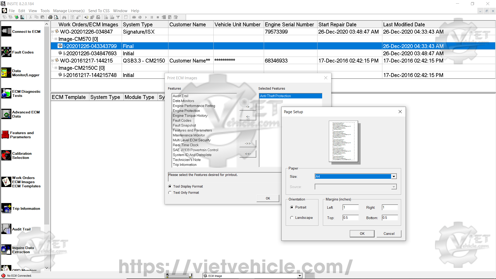
Figure 1.6 – Page setup
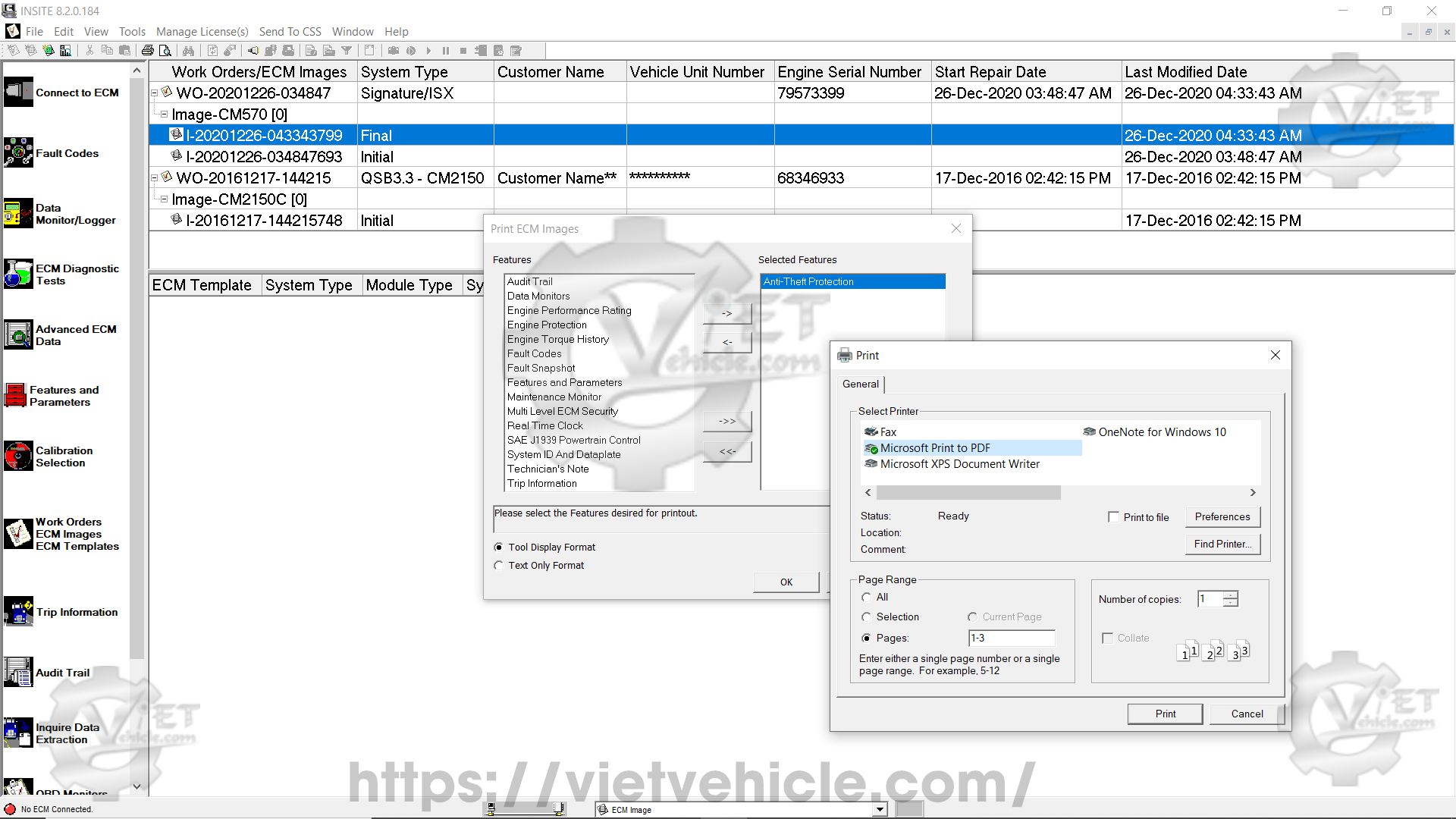
Figure 1.7 – Print to PDF file
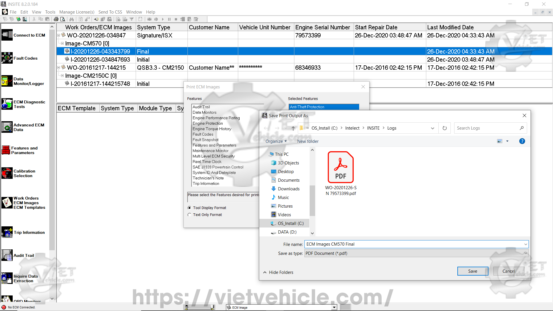
Figure 1.8 – Save print output as
Export image(s) to external file
Select this option to export ECM images to Comma Separated Values (.csv) or Text (.txt) format. An Export Location window will appear, allowing you to choose a file location and edit the file name. The default name format is “I-” followed by the year, month, day, hour, minute, and second when the work order was created
Example: “I-20201228-132845547” was created on December 28, 2020, at 01:28:45 PM.
Exported files can be opened using third-party applications such as Microsoft Excel. However, .csv and .txt files cannot be imported back into INSITE™.
Example downloads:
.csv file: “I-20201228-132845547.csv”
.txt file: “I-20201228-133457184.txt”
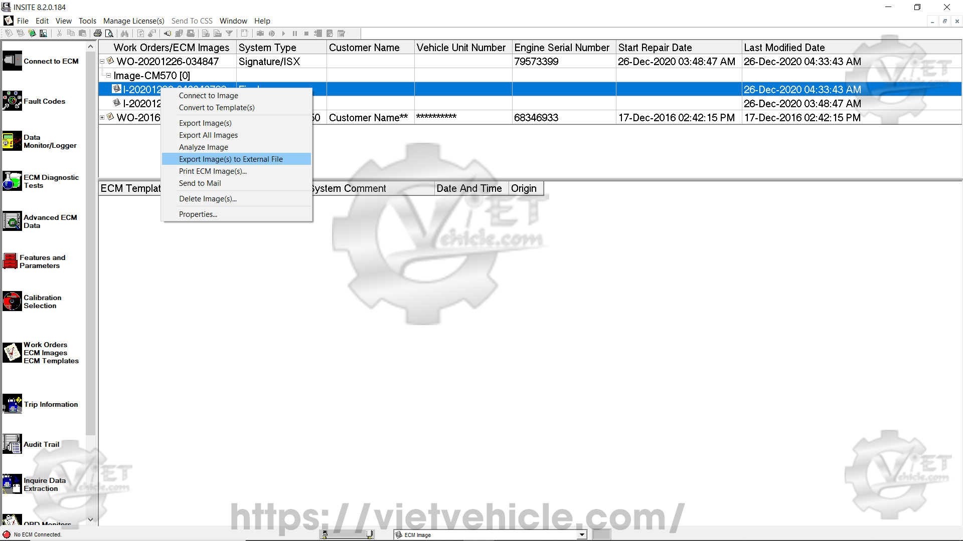
Figure 1.9 – Export image(s) to external file
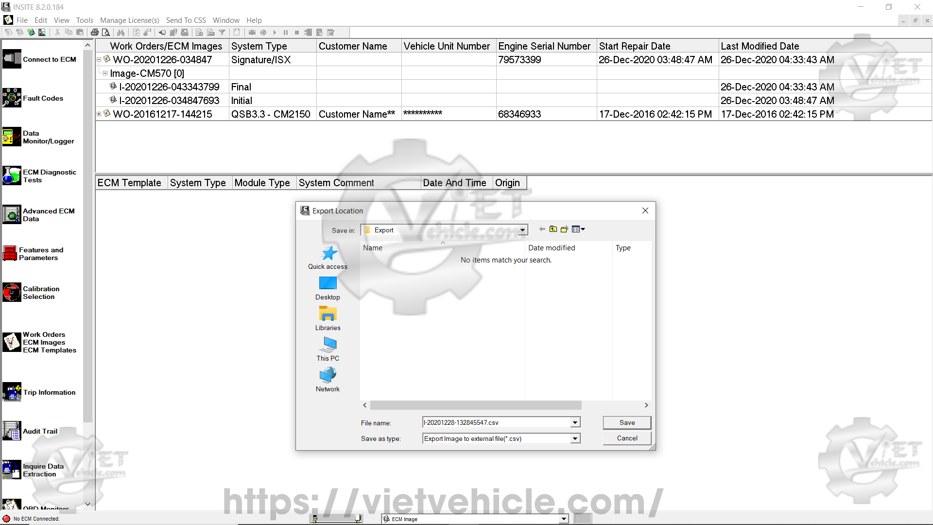
Figure 2.1 – Export location
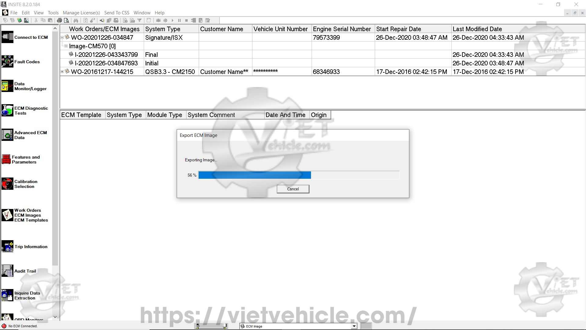
Figure 2.2 – Exporting image
Analyze image
Select this option to analyze ECM images using Image Analyzer for individual parameters and export selected features.
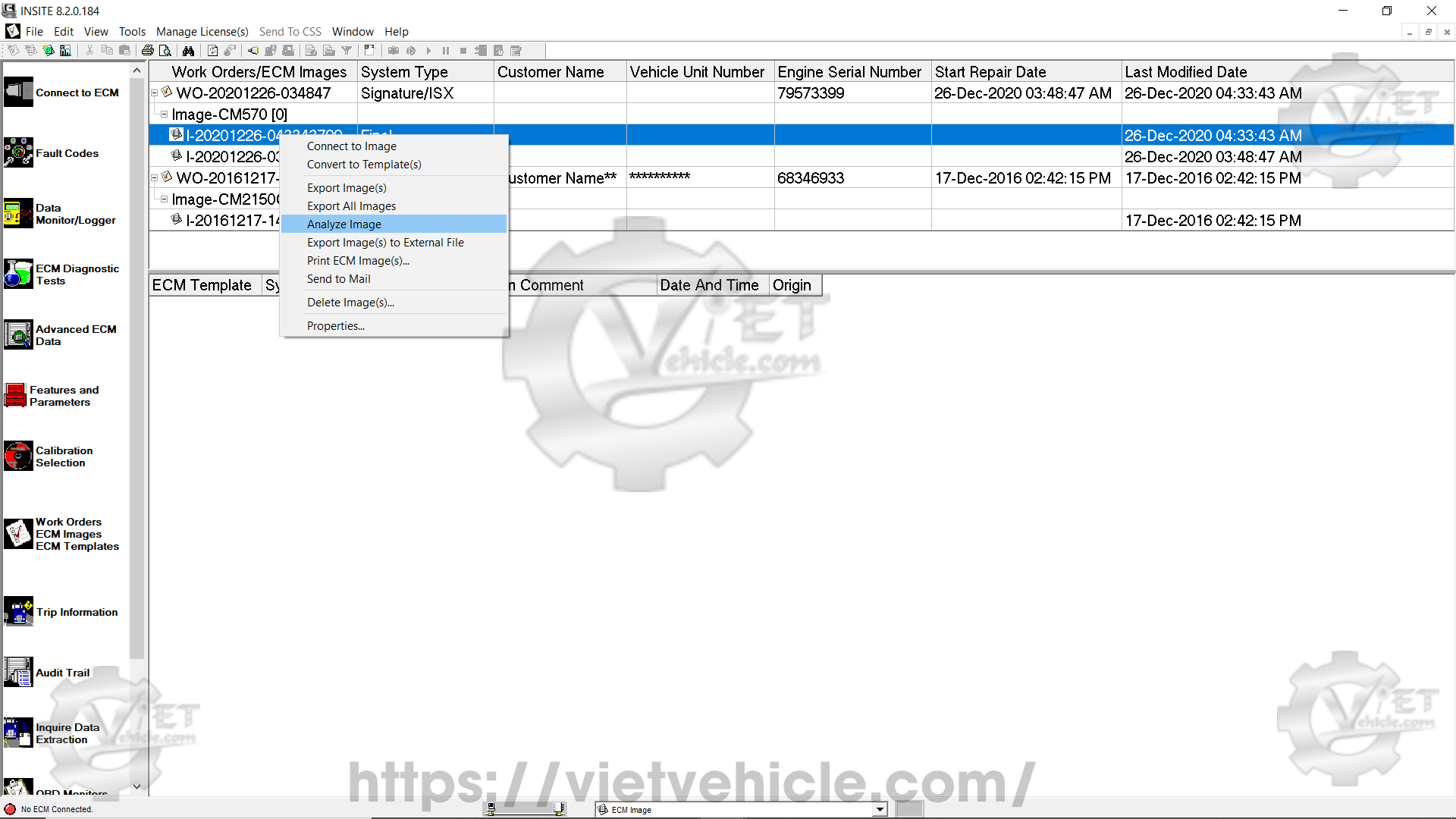
Figure 2.3 – Analyze image
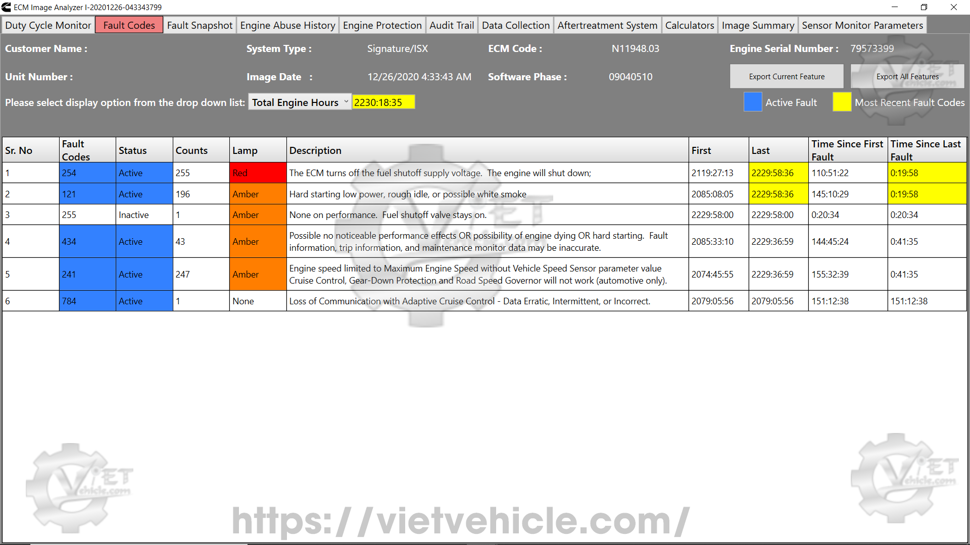
Figure 2.4 – Image analyzer
This version improves readability and organization while maintaining all technical details. Let me know if you need any additional adjustments!
Contact Us
Whatsapp: +84.858.966.333
Facebook: VIETVehicle Remote Delete Service
YouTube: VIETVehicle – ECM Delete Tuning
Tiktok: VIETVehicle.com
Website: VIETVehicle.com

