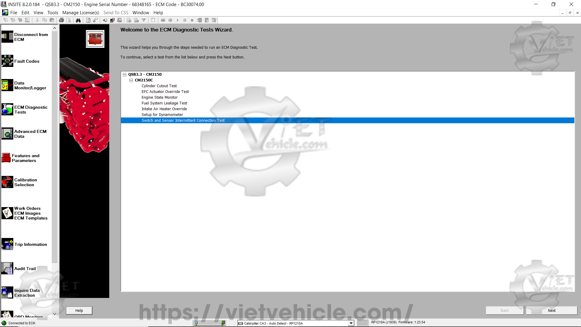
Figure 1.1 – ECM diagnostic tests
About
The switch and sensor intermittent connection test helps identify wiring connection issues that are difficult to detect. This test displays switch and sensor values as read from the ECM. Up to five switches or sensors can be tested at a time. Once the test begins, a bar graph displays the real-time values of the selected components. While the test is running, wires can be gently manipulated by twisting, bending, and pulling them. Any changes in switch or sensor values are displayed on the test screen.
Initial conditions
Vehicle stationary (if applicable)
Engine off
Attempt to recreate the conditions when the issue was originally observed (e.g., engine speed, temperature, and vehicle speed)
Performing the test
Open Cummins INSITE and connect to the engine’s diagnostic port. (Read More: How to connect CUMMINS engines using Cummins INSITE Software.)
Select Switch and Sensor Intermittent Connection Test from the ECM diagnostic tests window (refer to Figure 1.1), then click Next.
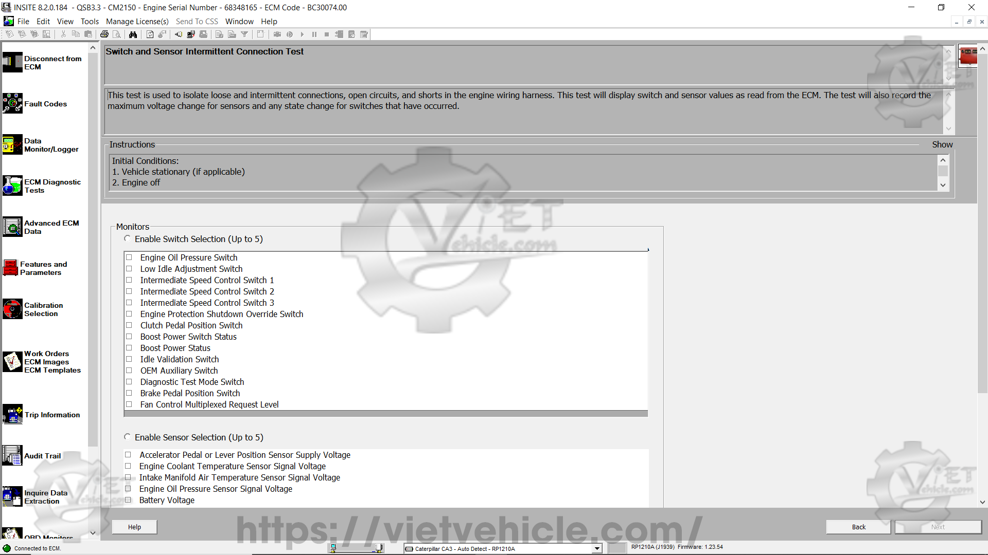
Figure 1.2 – Switch and sensor intermittent connection test
Choose up to five switches or sensors to test, then click Next.
Note: Sensors and switches cannot be tested together in a single session.
Sensor settings – enabling sensor selection
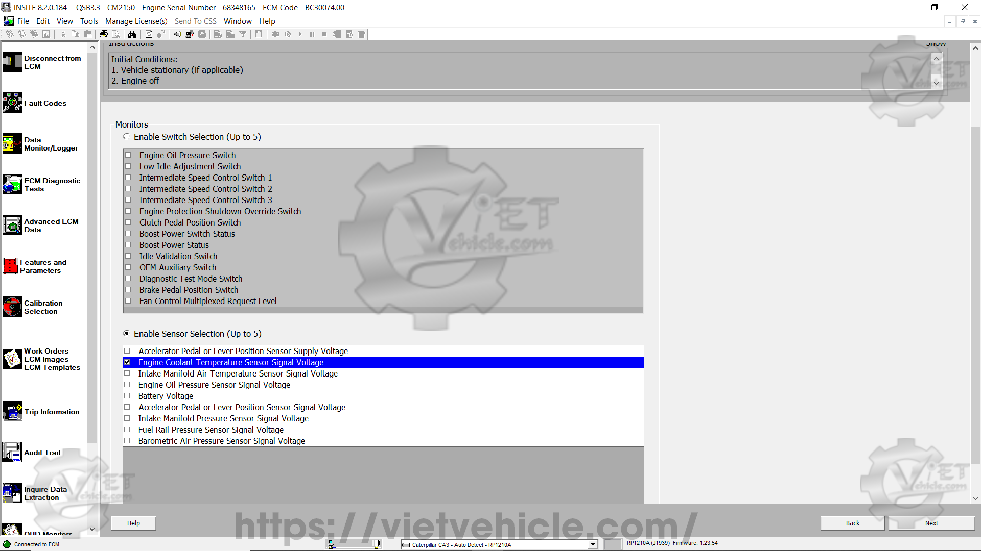
Figure 1.3 – Enable sensor selection
The test displays the name of each selected sensor, determines an initial value, and lists it in the Baseline column.
If needed, adjust the Voltage Range before starting the test using the up/down controls. The voltage range is added and subtracted from the baseline value to define the Out of Range limits on the graph. This adjustment affects the sensitivity of the monitored sensor.
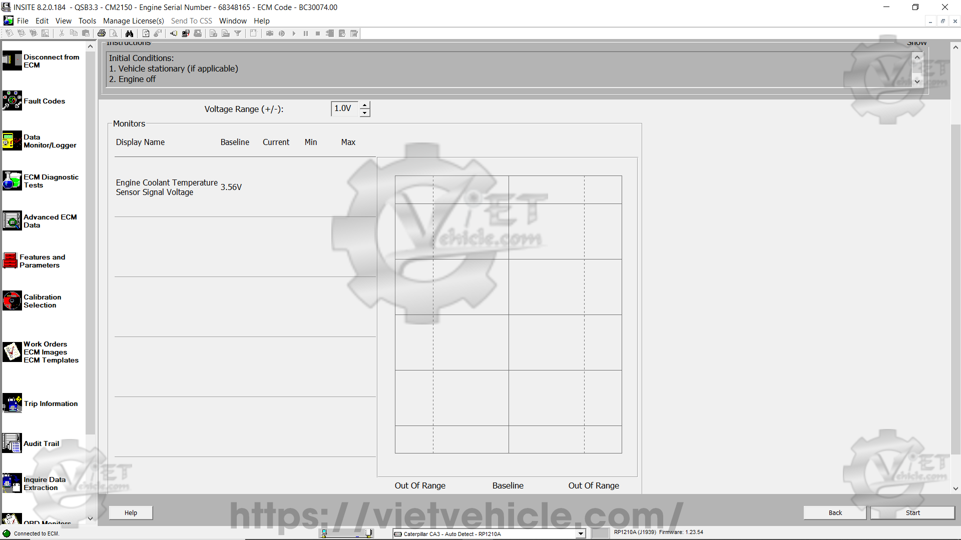
Figure 1.4 – Baseline (3.56V)
Click Start to begin the test.
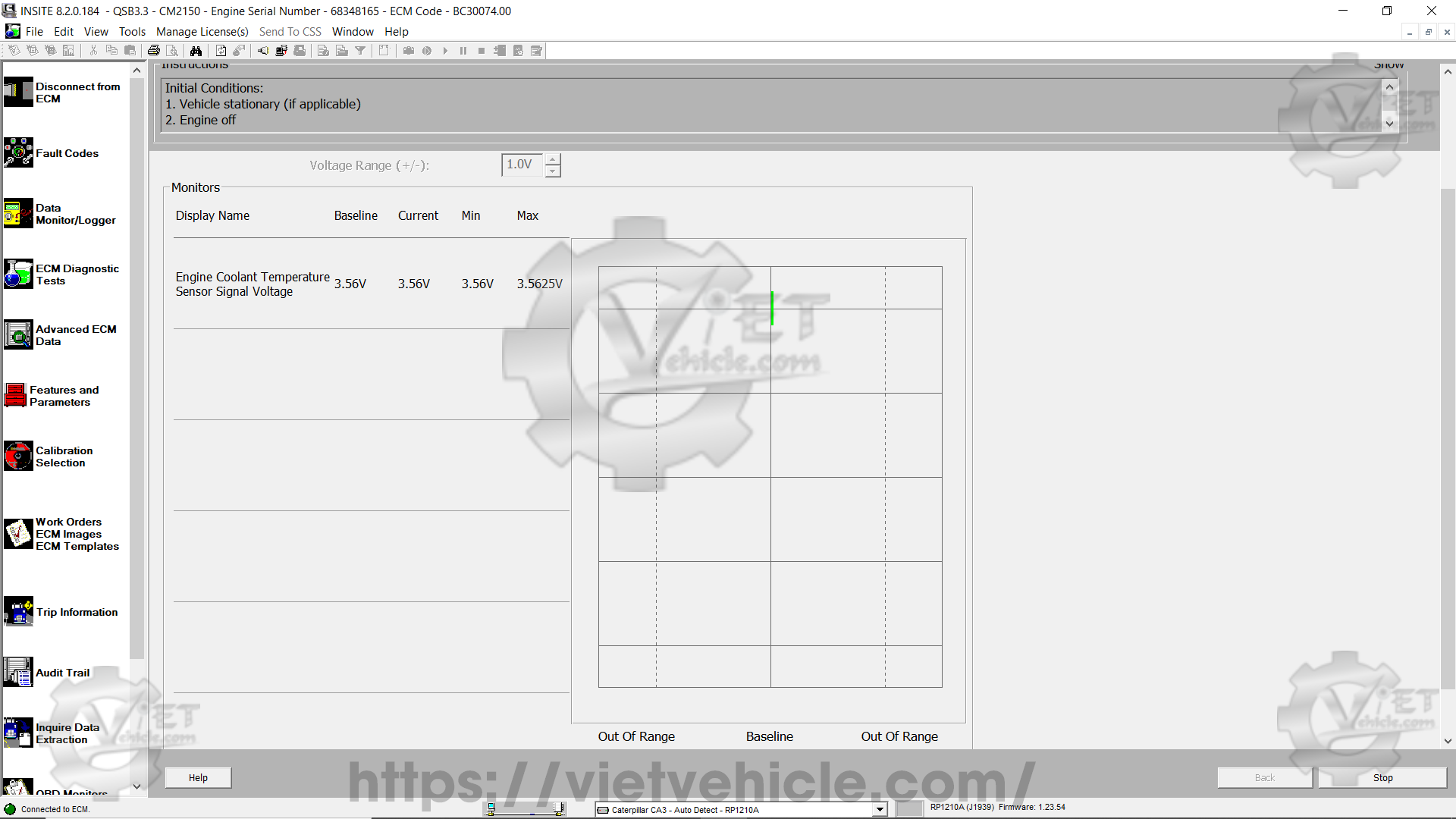
Figure 1.5 – Current (Min/Max 3.56V)
Start at the sensor being tested and work backward through the wiring harness to the ECM. Gently twist, bend, and pull on the wires and connections.
Changes in sensor values appear in real-time. The Current column continuously updates numerical values while the bar graph reflects these changes.
If the sensor value exceeds the voltage range, the bar graph turns red instead of green.
The largest voltage fluctuations are displayed in the Min and Max columns.
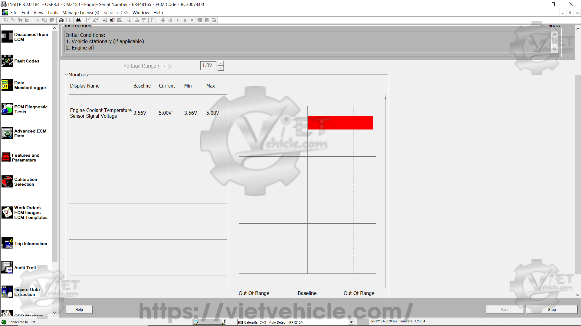
Figure 1.6 – Out of range (5.00V)
Click Stop to freeze values on the screen.
Click Start again to reset the display and continue testing, or click Back to return to the previous screen.
Click Back again to close the test.
Switch settings – enabling switch selection
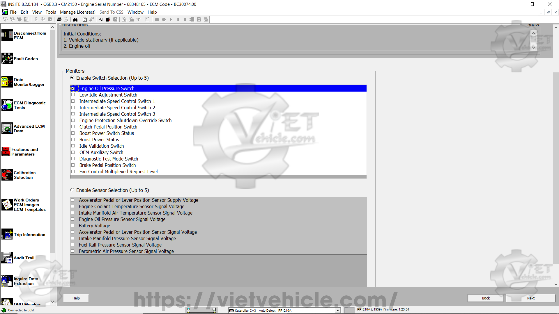
Figure 1.7 – Enable switch selection
The test displays the name of each selected switch, determines its initial status, and lists it in the Baseline column.
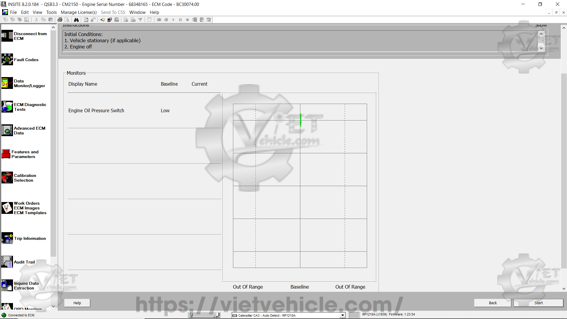
Figure 1.8 – Baseline (Low)
Click Start to begin the test.

Figure 1.9 – Current (Low)
Start at the switch being tested and work backward through the wiring harness to the ECM. Gently twist, bend, and pull on the wires and connections.
Changes in switch status appear in real-time in the Current column and on the bar graph.
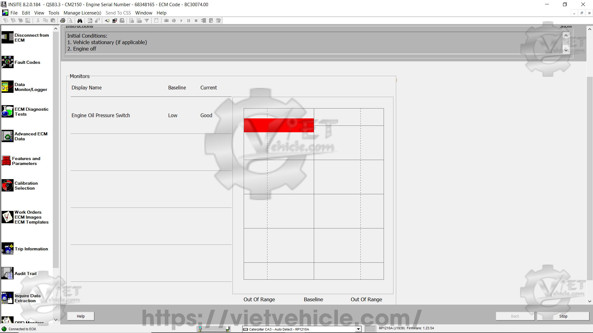
Figure 2.1 – Out of range (Good)
Click Stop to freeze the values on the screen.
Click Start again to reset the test screen and continue testing if needed.
When finished, click Back to return to the previous screen.
Click Back again to close the test.
Additional information
For sensor monitoring: The Out of Range limits can be adjusted before starting the test.
Maximum and minimum values: These are displayed on-screen and can be viewed by hovering over the indicator with the mouse.
Faster sample rate: The fewer parameters being monitored, the faster the data refreshes.
Engine running considerations: Normal fluctuations in sensor data can occur when the engine is running, potentially affecting test results.
Example: A truck cooling down will show exhaust temperature changes even if the wiring is intact.
Intermittent issues: Wiring problems usually appear as rapid voltage fluctuations.
In-motion testing: If the issue does not appear while stationary, rerun the test while the vehicle is in operation.
Contact Us
Whatsapp: +84.858.966.333
Facebook: VIETVehicle Remote Delete Service
YouTube: VIETVehicle – ECM Delete Tuning
Tiktok: VIETVehicle.com
Website: VIETVehicle.com


